This notebook continues from Lab2 Part 1 - Single Motor Control.ipynb. Make sure you’ve completed Task 1 (hardware connection) and Task 2 (single motor control) there first — this notebook assumes you already know your COM port and are comfortable with basic position control.
What you will do
Two Motor Control
Assign unique IDs to each motor so they can be addressed independently
Move two motors to different target angles simultaneously
Command each motor to follow a different sine wave and compare the results
When you finish Task 3, close this notebook and open Lab2 Problems.ipynb to work on the problems.
# ── Session setup — run this cell at the start of every session ──────────────
import time
import numpy as np
import matplotlib.pyplot as plt
import matplotlib.gridspec as gridspec # for more complex figure layouts
from Lab2_helpers import *

# ── Update these values to match your setup ─────────────────────────────────
PORT       = "COM4"   # from lerobot-find-port in Task 1 (see Lab2 Part 1)
MOTOR_ID_1 = 1         # first motor
MOTOR_ID_2 = 2         # second motor (after re-ID in Task 3.1 below)

print("Lab 2 Part 2 ready.")
Lab 2 Part 2 ready.
Control Two Motors
Assign a Unique ID to the Second Motor
Every motor on the same bus cable must have a unique ID (a number from 1 to 253). Motors arrive from the factory with ID = 1. Before you can control two motors independently, you need to change one motor’s ID so the two motors no longer share the same number.
Before running the cell below:
Disconnect the first motor from the bus adapter
Connect only the second motor to the adapter
Why connect only one motor at a time? If two motors share the same ID, they both respond to every command — you cannot address them separately. Assigning IDs with a single motor connected prevents this conflict.
The cell below calls assign_motor_id(port, existing_ids) from Lab2_helpers.py. It first scans the bus and reads the motor’s current ID automatically (so you don’t need to already know it), prints it, then prompts you to type the new ID. You can find the prompt on the top of VS code. It refuses to assign an ID that’s already in existing_ids (the other motor’s ID), so you can’t accidentally create the same conflict you’re trying to avoid — it will just ask you to try again.
Under the hood it uses two smaller helpers you can also call directly: scan_motor_id(port) to detect a connected motor’s current ID, and write_motor_id(port, current_id, new_id, existing_ids) to perform the actual write. There’s also a matching read_motor_id(port, motor_id) you can use afterward to double-check which ID a motor is actually using, once you know it.
After running, power-cycle the motor (unplug and re-plug the 12V supply) to save the new ID permanently.
# Connect only the motor you want to re-ID before running this cell.
# This scans the bus to find the motor's current ID, then prompts you (in the
# input box that appears above the notebook) to type the new ID.
#
# existing_ids lists the IDs already assigned to other motors on the bus --
# assign_motor_id refuses to reuse one of these, so you can't accidentally
# give two motors the same ID.
NEW_ID = assign_motor_id(PORT, existing_ids=[MOTOR_ID_1])
Found motor with ID 2.
Motor ID is already 2. No change made.
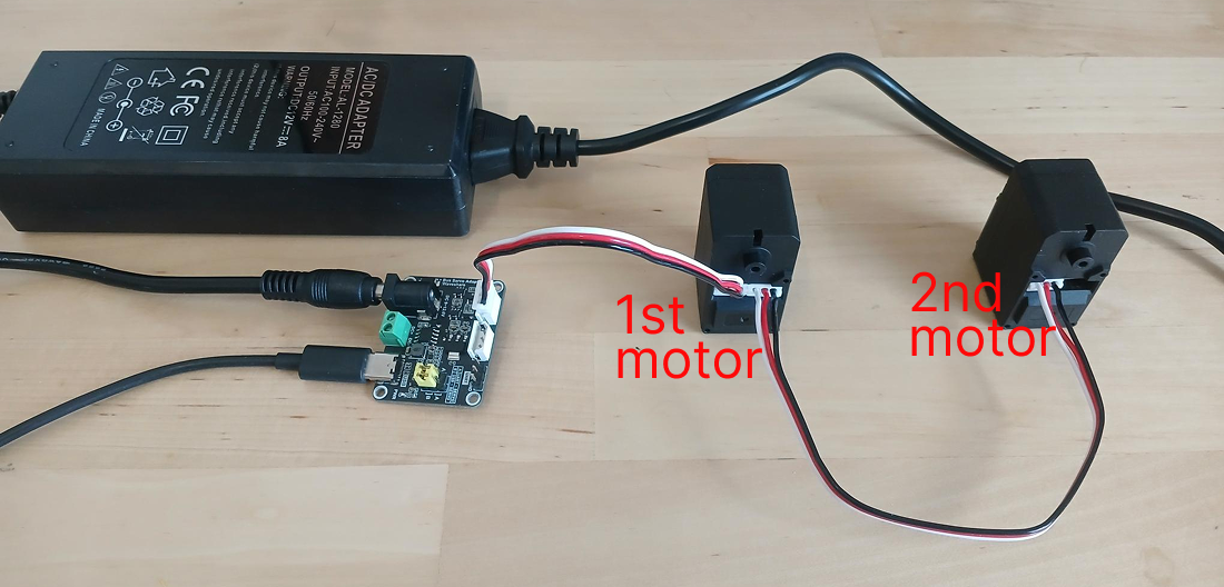
Now reconnect both motors in a daisy-chain: the first motor connects to the adapter, and the second motor connects to the first motor’s pass-through port using another 3-pin cable. Only one USB cable goes to your laptop — the bus handles communication to all motors.
This is one of the key advantages of a bus servo system: you can chain many motors together with just two wires and still address each one by its unique ID.
Your setup should look like something shown in the following picture
Two-Motor Control
Two motors on the same bus use the same helper functions from Lab2_helpers.py you already used in Part 1 — you just pass a list of two motor IDs to connect_motors, and two angles to write_angles, instead of one:
| Function | What it does |
|---|---|
connect_motors(port, [id1, id2]) | Opens a connection to both motors and enables position control. Returns a shared bus object. |
write_angles(bus, deg1, deg2) | Commands both motors to their target angles simultaneously in one packet. |
read_angles(bus) | Reads both motors’ current angles. Returns (angle1, angle2) in degrees. |
disconnect_motors(bus) | Disables torque on both motors and closes the connection. |
Nothing about these functions is specific to “two” — the same calls work for three motors (and beyond) later in the course.
# The same connect_motors / write_angles / read_angles / disconnect_motors helpers
# from Part 1 are used here for two motors. See Lab2_helpers.py for the full implementation.


# Sanity check — connect to both motors and read their current angles.
# Both should report a value close to 0° if the motors are resting at home position.
# If you get a connection error, check that both motors are powered and daisy-chained.
bus2 = connect_motors(PORT, [MOTOR_ID_1, MOTOR_ID_2])
d1, d2 = read_angles(bus2)
print(f"Motor 1: {d1:.1f}°")
print(f"Motor 2: {d2:.1f}°")
disconnect_motors(bus2)
print("Both motors ready.")
Motor 1: 0.4°
Motor 2: 0.1°
Motors disconnected.
Both motors ready.
Move Two Motors to Different Angles Simultaneously
Both motors receive their target angles in a single command packet — the adapter broadcasts both targets at once so both motors begin moving at exactly the same instant. This is called a synchronous write and is how real robot controllers coordinate multiple joints.
Change TARGET_1 and TARGET_2 to try different combinations. Notice that both motors start and stop simultaneously regardless of how far each one has to travel — the motor with the larger move simply takes longer to arrive.
TARGET_1 = 60.0    # degrees — target for motor 1
TARGET_2 = -45.0   # degrees — target for motor 2 (opposite direction)
RECORD_MOVE_SEC = 3.0 # seconds to record the movement response

print(f"Motor 1 target : {TARGET_1}°")
print(f"Motor 2 target : {TARGET_2}°")

bus2 = connect_motors(PORT, [MOTOR_ID_1, MOTOR_ID_2])

# Return both motors to 0° first
write_angles(bus2, 0.0, 0.0)
# Wait for motors to reach 0° before moving to new targets
time.sleep(2.0)

# target seconds per sample (50 Hz)
dt_m = 1.0 / 50
#lists to record the time and positions of both motors
t_move_list, pos1_list, pos2_list = [], [], []

write_angles(bus2, TARGET_1, TARGET_2)

# Record the movement response for RECORD_MOVE_SEC seconds
t0 = time.time()
while True:
    tick  = time.time() # timestamp for this sample
    t_now = tick - t0
    if t_now >= RECORD_MOVE_SEC:
        break
    d1, d2 = read_angles(bus2) # Read the current angles of both motors
    t_move_list.append(t_now)
    pos1_list.append(d1) # Record the position of motor 1
    pos2_list.append(d2) # Record the position of motor 2
    elapsed = time.time() - tick # Time taken to read angles and record data
    if elapsed < dt_m: time.sleep(dt_m - elapsed) # Wait until the next sample time

t_move    = np.array(t_move_list)
pos1_move = np.array(pos1_list)
pos2_move = np.array(pos2_list)

achieved_hz = len(t_move) / t_move[-1] if len(t_move) > 1 else float("nan")
print(f"\nRecorded {len(t_move)} samples over {t_move[-1]:.2f} s (~{achieved_hz:.0f} Hz achieved).")
print(f"Final positions:")
print(f"  Motor 1: {pos1_move[-1]:.2f}°  (target {TARGET_1}°)")
print(f"  Motor 2: {pos2_move[-1]:.2f}°  (target {TARGET_2}°)")

write_angles(bus2, 0.0, 0.0) # Return to 0° before disconnecting
time.sleep(1.5) # Wait for motors to reach 0° before disconnecting
disconnect_motors(bus2)
Motor 1 target : 60.0°
Motor 2 target : -45.0°
Recorded 140 samples over 2.99 s (~47 Hz achieved).
Final positions:
Motor 1: 59.85° (target 60.0°)
Motor 2: -44.91° (target -45.0°)
Motors disconnected.
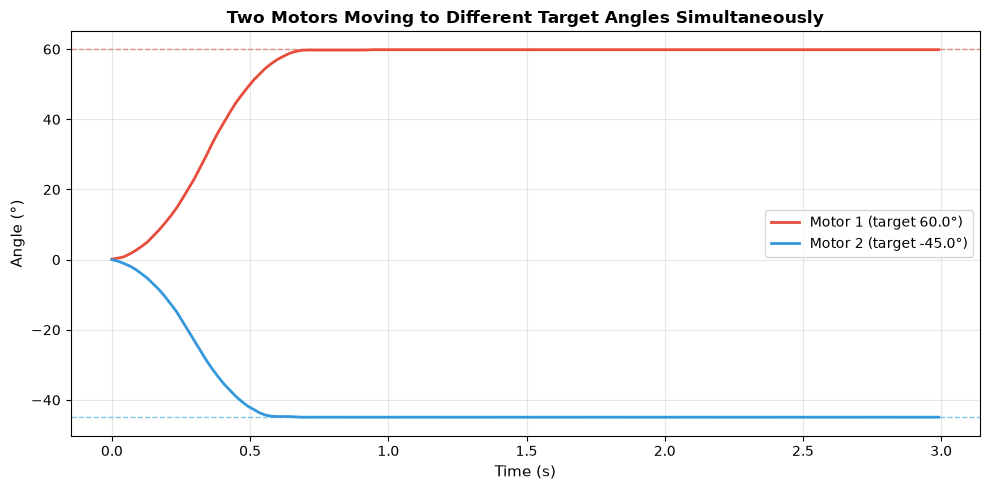
The plot below shows both motors’ positions over time. The dashed lines mark the target angles. Things to look for:
Both motors start moving at the same instant (synchronous command)
Each motor follows a smooth trapezoidal velocity profile — it accelerates, cruises, then decelerates
The motor with the larger travel distance takes longer to arrive at its target
fig, ax = plt.subplots(figsize=(10, 5))

ax.plot(t_move, pos1_move, color="#e74c3c", linewidth=2, label=f"Motor 1 (target {TARGET_1}°)")
ax.plot(t_move, pos2_move, color="#3498db", linewidth=2, label=f"Motor 2 (target {TARGET_2}°)")
ax.axhline(TARGET_1, color="#e74c3c", linewidth=1, linestyle="--", alpha=0.6)
ax.axhline(TARGET_2, color="#3498db", linewidth=1, linestyle="--", alpha=0.6)

ax.set_xlabel("Time (s)", fontsize=11)
ax.set_ylabel("Angle (°)", fontsize=11)
ax.set_title("Two Motors Moving to Different Target Angles Simultaneously",
             fontsize=12, fontweight="bold")
ax.legend(fontsize=10)
ax.grid(True, alpha=0.3)
plt.tight_layout()
plt.savefig("two_motor_angles.png", dpi=150, bbox_inches="tight")
plt.show()
print("Plot saved as two_motor_angles.png")
Plot saved as two_motor_angles.png
Two Motors Following Different Sine Waves
Each motor tracks its own independent sine wave, both commanded in the same write_angles call every 20 ms. This demonstrates real-time coordinated multi-joint control — the same principle the SO-Arm 101 will use when you control it as a complete robot later in the course.
| Motor 1 | Motor 2 | |
|---|---|---|
| Amplitude | 45° | 25° |
| Frequency | 0.4 Hz | 0.8 Hz |
| Period | 2.5 s | 1.25 s |
Motor 2 oscillates twice as fast with a smaller swing. Because both are commanded in the same packet each step, their motions remain time-synchronized throughout the run.
# ── Parameters — try changing these ──────────────────────────────────────────
AMP1, FREQ1 = 45.0, 0.4   # Motor 1: larger swing, slower oscillation
AMP2, FREQ2 = 25.0, 0.8   # Motor 2: smaller swing, faster oscillation
DUAL_DURATION = 10.0       # total run time (seconds)
DUAL_HZ       = 50         # *target* command/recording rate (Hz) -- see note below

# target seconds per sample (50 Hz)
dt_d = 1.0 / DUAL_HZ
# Lists to record the time, reference angles, and actual angles of both motors
t_d_list, ref1_list, ref2_list, act1_list, act2_list = [], [], [], [], []

bus2 = connect_motors(PORT, [MOTOR_ID_1, MOTOR_ID_2])

print(f"Motor 1: A={AMP1}°  f={FREQ1} Hz  (period = {1/FREQ1:.2f} s)")
print(f"Motor 2: A={AMP2}°  f={FREQ2} Hz  (period = {1/FREQ2:.2f} s)")
print("Running — do not interrupt until 'Done' appears...")

t_start = time.time()
while True:
    tick  = time.time()
    t_now = tick - t_start
    if t_now >= DUAL_DURATION:
        break

    # Compute the reference angle for each motor at this instant
    r1 = AMP1 * np.sin(2 * np.pi * FREQ1 * t_now)
    r2 = AMP2 * np.sin(2 * np.pi * FREQ2 * t_now)

    write_angles(bus2, r1, r2)      # command both motors simultaneously
    a1, a2 = read_angles(bus2)      # read both motors' actual positions

    # Store this sample
    t_d_list.append(t_now)
    ref1_list.append(r1); ref2_list.append(r2)
    act1_list.append(a1); act2_list.append(a2)

    # Sleep out the remainder of this period, if any is left
    elapsed = time.time() - tick
    if elapsed < dt_d:
        time.sleep(dt_d - elapsed)

t_d    = np.array(t_d_list)
ref1_d = np.array(ref1_list);  ref2_d = np.array(ref2_list)
act1_d = np.array(act1_list);  act2_d = np.array(act2_list)

write_angles(bus2, 0.0, 0.0)    # return both motors to 0° before disconnecting
time.sleep(1.5)
disconnect_motors(bus2)

achieved_hz = len(t_d) / t_d[-1] if len(t_d) > 1 else float("nan")
print(f"Done. Recorded {len(t_d)} samples over {t_d[-1]:.2f} s "
      f"(~{achieved_hz:.0f} Hz achieved vs. {DUAL_HZ} Hz requested -- "
      "write+read round trips over the bus are the limiting factor).")
print("Run the next cell to plot the results.")
Motor 1: A=45.0° f=0.4 Hz (period = 2.50 s)
Motor 2: A=25.0° f=0.8 Hz (period = 1.25 s)
Running — do not interrupt until 'Done' appears...
Motors disconnected.
Done. Recorded 188 samples over 9.97 s (~19 Hz achieved vs. 50 Hz requested -- write+read round trips over the bus are the limiting factor).
Run the next cell to plot the results.
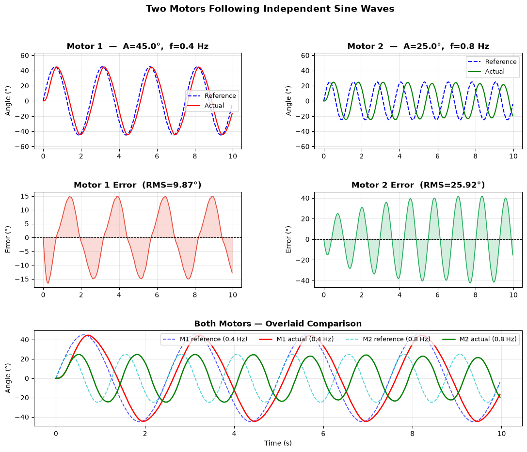
The six-panel plot below shows:
Top row: reference vs. actual trajectory for each motor
Middle row: tracking error for each motor, with the RMS value in the title
Bottom row: both motors overlaid on the same axes for direct comparison
Notice that Motor 2 (faster, 0.8 Hz) accumulates larger tracking error than Motor 1 (slower, 0.4 Hz) — a clear demonstration that a higher command frequency demands more from the actuator.
fig = plt.figure(figsize=(13, 10))
gs  = gridspec.GridSpec(3, 2, figure=fig, hspace=0.45, wspace=0.35)

# ── Motor 1 tracking ──────────────────────────────────────────────────────────
ax1 = fig.add_subplot(gs[0, 0])
ax1.plot(t_d, ref1_d, "b--", linewidth=1.5, label="Reference")
ax1.plot(t_d, act1_d, "r-",  linewidth=1.5, label="Actual")
ax1.set_title(f"Motor 1  —  A={AMP1}°,  f={FREQ1} Hz", fontweight="bold")
ax1.set_ylabel("Angle (°)")
ax1.legend(fontsize=9); ax1.grid(True, alpha=0.3)
ax1.set_ylim(-AMP1*1.4, AMP1*1.4)

# ── Motor 2 tracking ──────────────────────────────────────────────────────────
ax2 = fig.add_subplot(gs[0, 1])
ax2.plot(t_d, ref2_d, "b--", linewidth=1.5, label="Reference")
ax2.plot(t_d, act2_d, "g-",  linewidth=1.5, label="Actual")
ax2.set_title(f"Motor 2  —  A={AMP2}°,  f={FREQ2} Hz", fontweight="bold")
ax2.set_ylabel("Angle (°)")
ax2.legend(fontsize=9); ax2.grid(True, alpha=0.3)
ax2.set_ylim(-AMP1*1.4, AMP1*1.4)   # same y-scale for easy comparison

# ── Error motor 1 ─────────────────────────────────────────────────────────────
err1 = act1_d - ref1_d
ax3  = fig.add_subplot(gs[1, 0])
ax3.plot(t_d, err1, color="#e74c3c", linewidth=1.2)
ax3.fill_between(t_d, err1, 0, alpha=0.2, color="#e74c3c")
ax3.axhline(0, color="black", linewidth=0.8, linestyle="--")
ax3.set_title(f"Motor 1 Error  (RMS={np.sqrt(np.mean(err1**2)):.2f}°)", fontweight="bold")
ax3.set_ylabel("Error (°)"); ax3.grid(True, alpha=0.3)

# ── Error motor 2 ─────────────────────────────────────────────────────────────
err2 = act2_d - ref2_d
ax4  = fig.add_subplot(gs[1, 1])
ax4.plot(t_d, err2, color="#27ae60", linewidth=1.2)
ax4.fill_between(t_d, err2, 0, alpha=0.2, color="#27ae60")
ax4.axhline(0, color="black", linewidth=0.8, linestyle="--")
ax4.set_title(f"Motor 2 Error  (RMS={np.sqrt(np.mean(err2**2)):.2f}°)", fontweight="bold")
ax4.set_ylabel("Error (°)"); ax4.grid(True, alpha=0.3)

# ── Both motors overlaid for comparison ───────────────────────────────────────
ax5 = fig.add_subplot(gs[2, :])
ax5.plot(t_d, ref1_d, "b--",  linewidth=1.3, alpha=0.7, label=f"M1 reference ({FREQ1} Hz)")
ax5.plot(t_d, act1_d, "r-",   linewidth=1.8, label=f"M1 actual ({FREQ1} Hz)")
ax5.plot(t_d, ref2_d, "c--",  linewidth=1.3, alpha=0.7, label=f"M2 reference ({FREQ2} Hz)")
ax5.plot(t_d, act2_d, "g-",   linewidth=1.8, label=f"M2 actual ({FREQ2} Hz)")
ax5.set_title("Both Motors — Overlaid Comparison", fontweight="bold")
ax5.set_xlabel("Time (s)"); ax5.set_ylabel("Angle (°)")
ax5.legend(ncol=4, fontsize=9, loc="upper right"); ax5.grid(True, alpha=0.3)

fig.suptitle("Two Motors Following Independent Sine Waves", fontsize=14, fontweight="bold")
plt.savefig("dual_sine_tracking.png", dpi=150, bbox_inches="tight")
plt.show()
print("Plot saved as dual_sine_tracking.png")
Plot saved as dual_sine_tracking.png
Next Steps
You’ve assigned unique IDs to two motors, moved them to independent targets simultaneously, and tracked two different sine waves at once.
Continue to Lab2 Problems.ipynb to apply what you’ve learned in Parts 1 and 2.